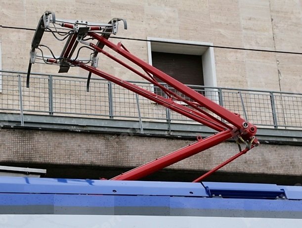
The pantograph
The pantograph is a current collector fitted to the roof of a railway vehicle so it can collect electricity from an overhead wire (catenary) in order to power equipment such as motors, electric heating, air conditioning and on-board ancillary devices. It is the most suitable for traction units due to the high speed and power requested.
In general, the pantograph comprises a hinged system (contact shoe), fitted to the base frame, and fastened to the top of the train by means of insulators. The contact shoe supports the collector head fitted with strips that are in direct contact with the catenary wire(s).
The hinged system allows the collector head to move freely in the vertical plane without losing contact with the overhead line. The contact strips are bars of conductive material (copper, steel, aluminium, carbon) and are the actual current collector, being in direct contact with the overhead wires. They are constructed using materials that can keep wear of the line to a minimum.
The pantograph, whose working height can reach 3 metres, is raised by compressed-air-operated devices and maintained at the required pressure against the overhead wire using preloaded springs or, as in the case of more modern imposed-force devices, a pneumatic controller that adjusts the amount of force to suit the running speed and thus improve collection quality.
Sample description and test purpose
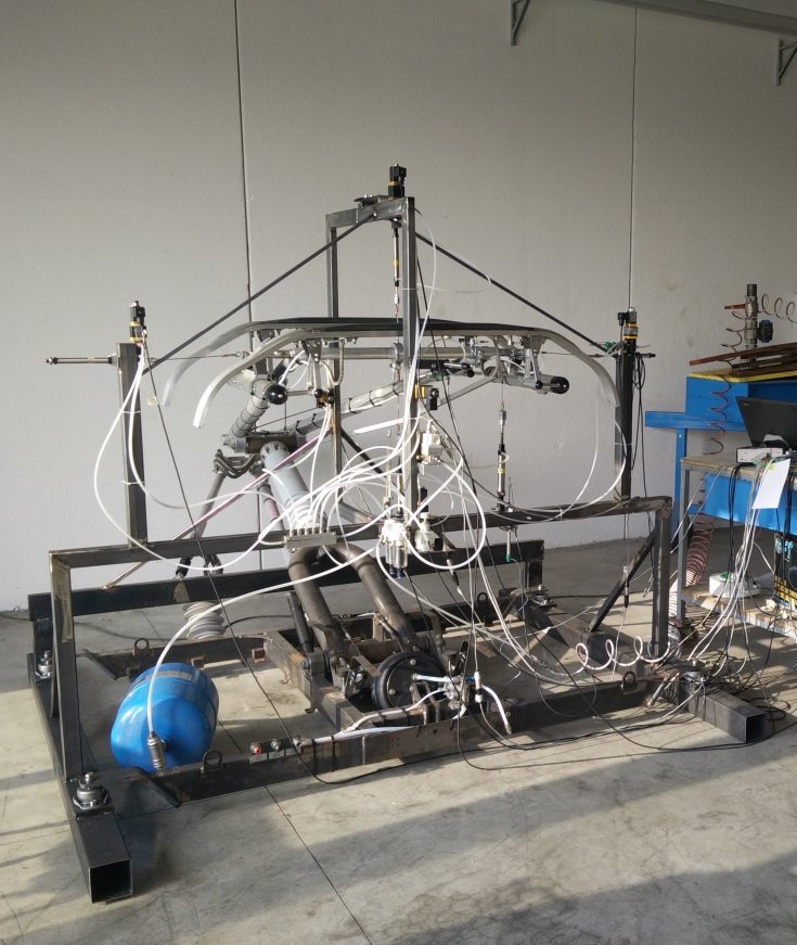
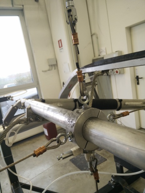
The test sample comprises a fully-assembled railway pantograph, complete with all electrical and mechanical components, installed on the supporting structure used when in service.
The purpose of the test is to assess the fatigue behaviour of the upper-arm welds and note any other phenomenon caused by fatigue during testing.
Test set-up
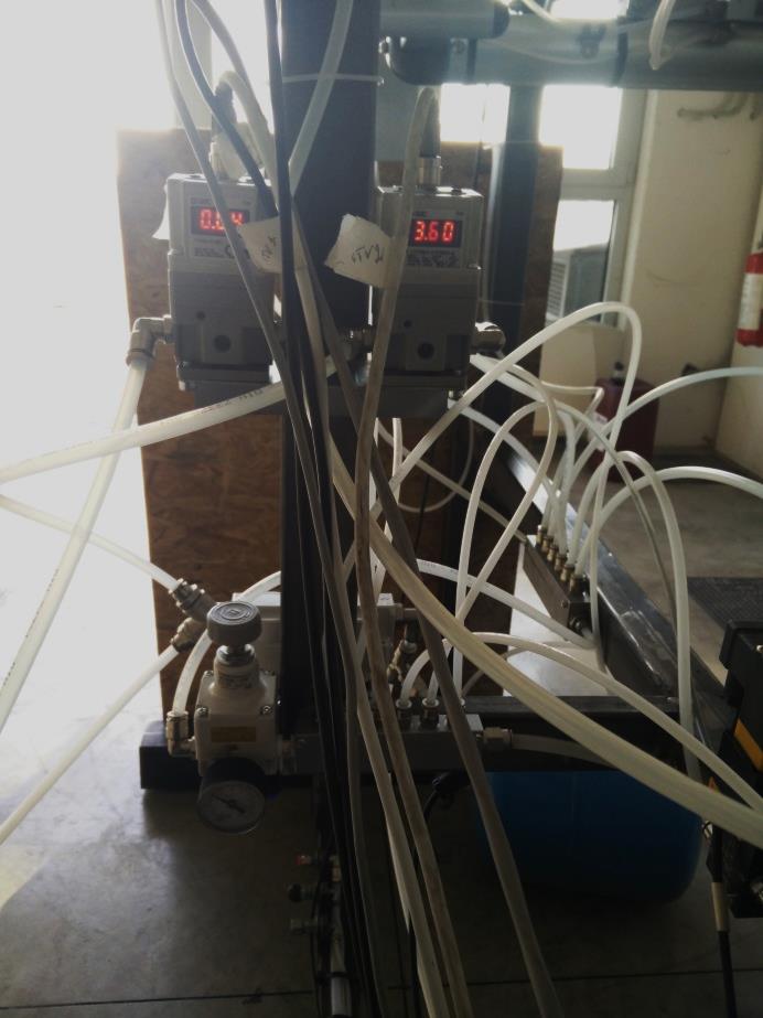
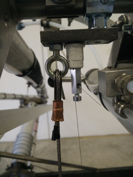
Test apparatus | Close-up of pressure monitoring systems |
 |  |
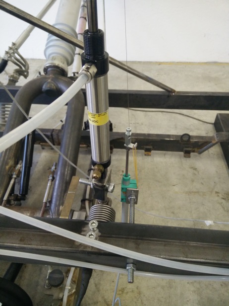
| Close-up of sensor and actuator fixings |
Since the pantograph's original raising system controls force but not position, a supporting frame was constructed that will support the sample under the most demanding conditions.
6 pneumatic pistons were connected to the arm supporting the contact strips in order to simulate the inertial forces generated by movement of the train.
A seventh piston, simulating the load generated by the contact with the cable, was also positioned on the arm, at a distance of 400 mm from the centre, in order to reproduce the worst-case contact position.
Displacement sensors were positioned close to the piston operating points in order measure the amplitude of oscillation and detect any load-induced deformation. All actuators and sensors were connected to a PLC controlled by in-house software. Data acquired was also sent to a PC for real-time monitoring and logging. Once again, an interface developed in-house was utilised.
Performing the test
The test was carried out according to specifications agreed with the customer that include the following main steps:
- Preliminary test with application of individual static loads; measurement of deflection and stress for each individual load;
- Simultaneous application of fatigue loads. The loads were applied at a frequency of approx. 2 Hz. The pairs of pistons operated at slightly different frequencies in order to be able to cover all possible load combinations. Fatigue test halted every 2 million cycles in order to measure deflection and visually inspect the pantograph for possible damage;
- At the end of the test, a careful visual inspection was performed of all pantograph components, in particular the upper arm, in order to check for possible damage or failure.
At no time during testing was any sign of failure or collapse noted of either the welds under examination or any other sample component.
Our thanks to the customer Production Group S.r.l. for granting permission to publish the details and photos of the test.


 Do you need more information about our services?